
DATPOL · FIRE SAFETY IN POLAND
Fire safety.
From design to maintenance.
Fire alarms, aspirating detection, smoke control, fire interfaces and fixed suppression. Coordinated protection for commercial buildings, industry, electrical rooms and server rooms.
Discuss your site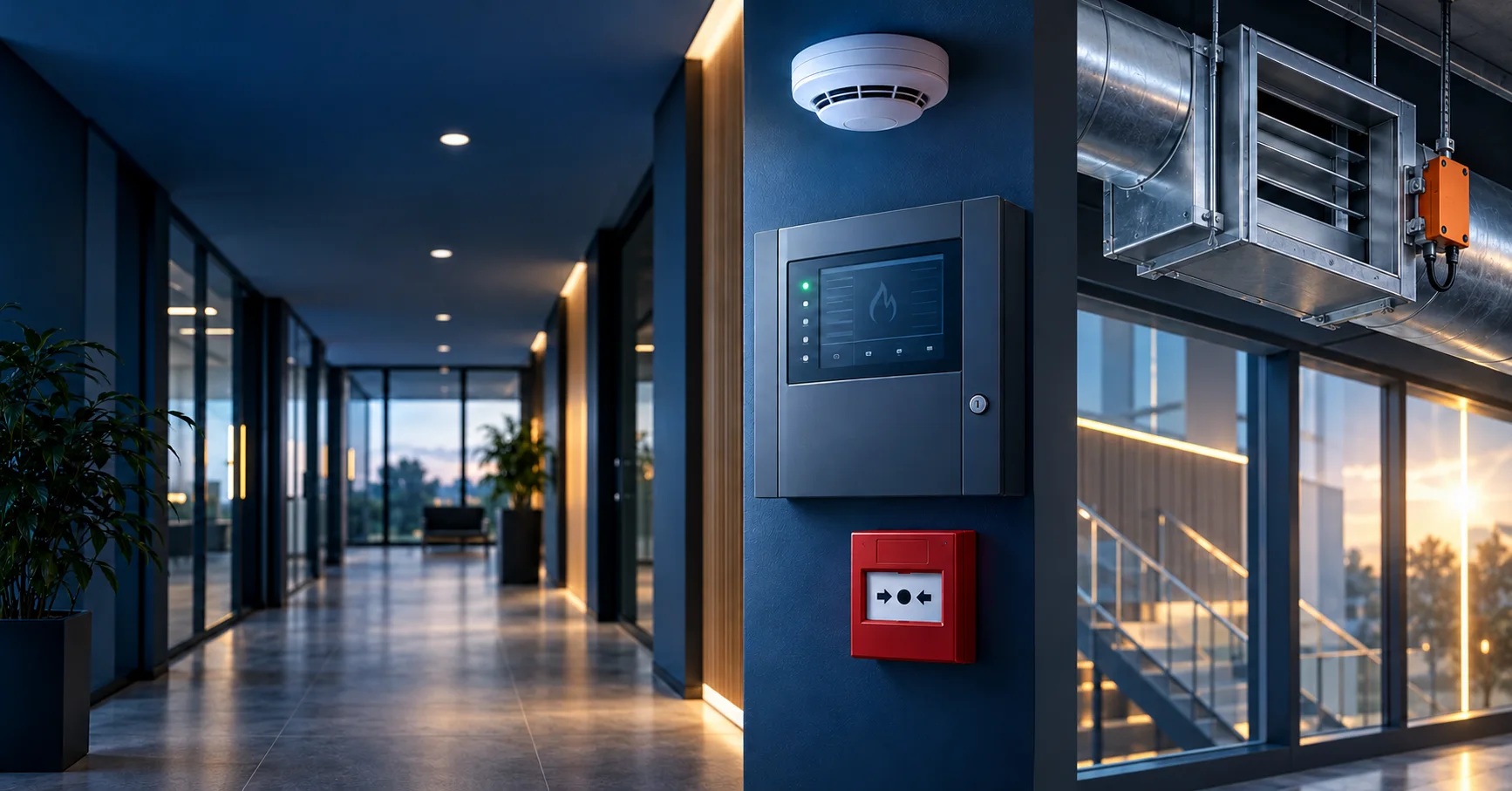
Contents — choose a section
- Survey, concept and design
- Fire detection and alarm systems
- Aspirating detection — VESDA, TITANUS and ASD
- Smoke control and smoke protection
- Fire-service electrical isolation — PWP
- Fire scenarios and cause-and-effect matrices
- Fire doors, shutters and compartmentation
- Fixed fire suppression systems
- Server-room and IT-room suppression
- Electrical switchboard and cabinet suppression
- Gas detection — GAZEX and related systems
- Standalone smoke, CO and gas alarms
- Remote panels for administrators and end users
- Fire alarm visualisation for operators and control rooms
- Installation, commissioning and acceptance
- Maintenance, inspections and fault repairs
- Polish regulations, standards and documents
- What should you prepare?
01 / DATPOL
Survey, concept and design
Our scope covers the investment lifecycle: reviewing existing protection, concept development, design, equipment selection, installation, commissioning, acceptance and maintenance. Responsibilities of the designer, fire-protection expert, installer and site operator are agreed before work starts.
- Survey: an inventory of panels, detectors, loops, power supplies, batteries, cables, actuators and documentation. We review faults, disablements and changes to room layouts.
- Building assessment: use and size, fire compartments, occupant numbers and evacuation needs, process hazards, equipment and insurer requirements.
- Protection concept: detection, alarms, smoke control, suppression and controls; system interfaces, normal supplies and standby power.
- Design: layouts, diagrams, calculations, routes and supports, zoning, equipment schedules, a cause-and-effect matrix and acceptance criteria. Fire-protection system designs require the appropriate approval.
A technical survey establishes risks and priorities. It does not replace a required expert assessment, design or authority decision. Upgrades include a phased work plan and arrangements for protection during outages.
02 / DATPOL
Fire detection and alarm systems
We select addressable or conventional systems for the building, environment and required coverage. Options include smoke, heat, multisensor, beam and specialist detectors, manual call points, audible and visual alarm devices, control panels and alarm transmission equipment.
The design addresses loop topology, short-circuit isolators, device identification, detection zones, fault supervision and power calculations. Detector selection follows the hazard and environment: steam, dust, air movement and ceiling height affect performance and unwanted-alarm risk.
Voice-alarm integration includes message content, zoning, priorities and consistency with the fire strategy. Requirements for fire detection, voice alarms and transmission to the Polish State Fire Service are assessed separately. An SMS or web dashboard does not replace mandatory fire-alarm transmission.
03 / DATPOL
Aspirating detection — VESDA, TITANUS and ASD
An aspirating smoke detection system (ASD) draws air from the protected area through sampling pipes and holes to a detector. Example product families include Xtralis VESDA and WAGNER TITANUS. The version selected depends on the application and sensitivity requirements; these names do not imply interchangeable equipment.
- Server rooms, electrical rooms, archives, high-bay buildings and inaccessible spaces, following airflow and hazard assessment.
- Sampling-network calculations, hole positions, transport time, appropriate sensitivity classes and warning/alarm thresholds.
- Airflow supervision, filtration, maintenance access and detection of blocked or leaking pipes.
- Tests at actual sampling points, documenting the response of the complete system rather than only the detector.
Early warning can help operators respond before a fire develops. Suppression release follows the design and cause-and-effect matrix; a preliminary warning should not automatically be treated as a release command.
04 / DATPOL
Smoke control and smoke protection
The scope covers natural and mechanical smoke exhaust and systems protecting escape routes against smoke, as defined in the design. Stairwells, halls, atria, garages, smoke zones and replacement-air paths are assessed together.
- Smoke vents and windows, actuators, panels, manual controls and standby supplies.
- Smoke-extract fans, ducts, smoke-control dampers and interfaces with normal ventilation.
- Replacement air, pressure-differential systems, door behaviour and evacuation conditions.
- Priority of the fire function over comfort ventilation, weather inputs and building controls.
- Testing movement, limit switches, supplies, fault signals and specified airflow or pressure performance.
An open vent alone does not demonstrate effective smoke control. Performance depends on the complete system, including replacement air and appropriate zoning.
05 / DATPOL
Fire-service electrical isolation — PWP
A Polish PWP fire-service electrical isolation system is designed as a complete disconnection function, not merely a red push-button near an entrance. The design identifies circuits to disconnect and equipment that must remain supplied during a fire.
All energy sources are considered: mains, generators, UPS, solar PV and battery storage. We assess status indication, control circuits, switching equipment, identification, activation locations and unintended re-energisation. Operating a PWP does not automatically remove voltage from every part of an installation, such as the PV DC side.
Selection includes documentation applicable to the product and configuration, including a national technical assessment and declaration of performance where required. CNBOP-PIB explains the product assessment framework. Tests follow an agreed isolation plan and record the actual installation response.
06 / DATPOL
Fire scenarios and cause-and-effect matrices
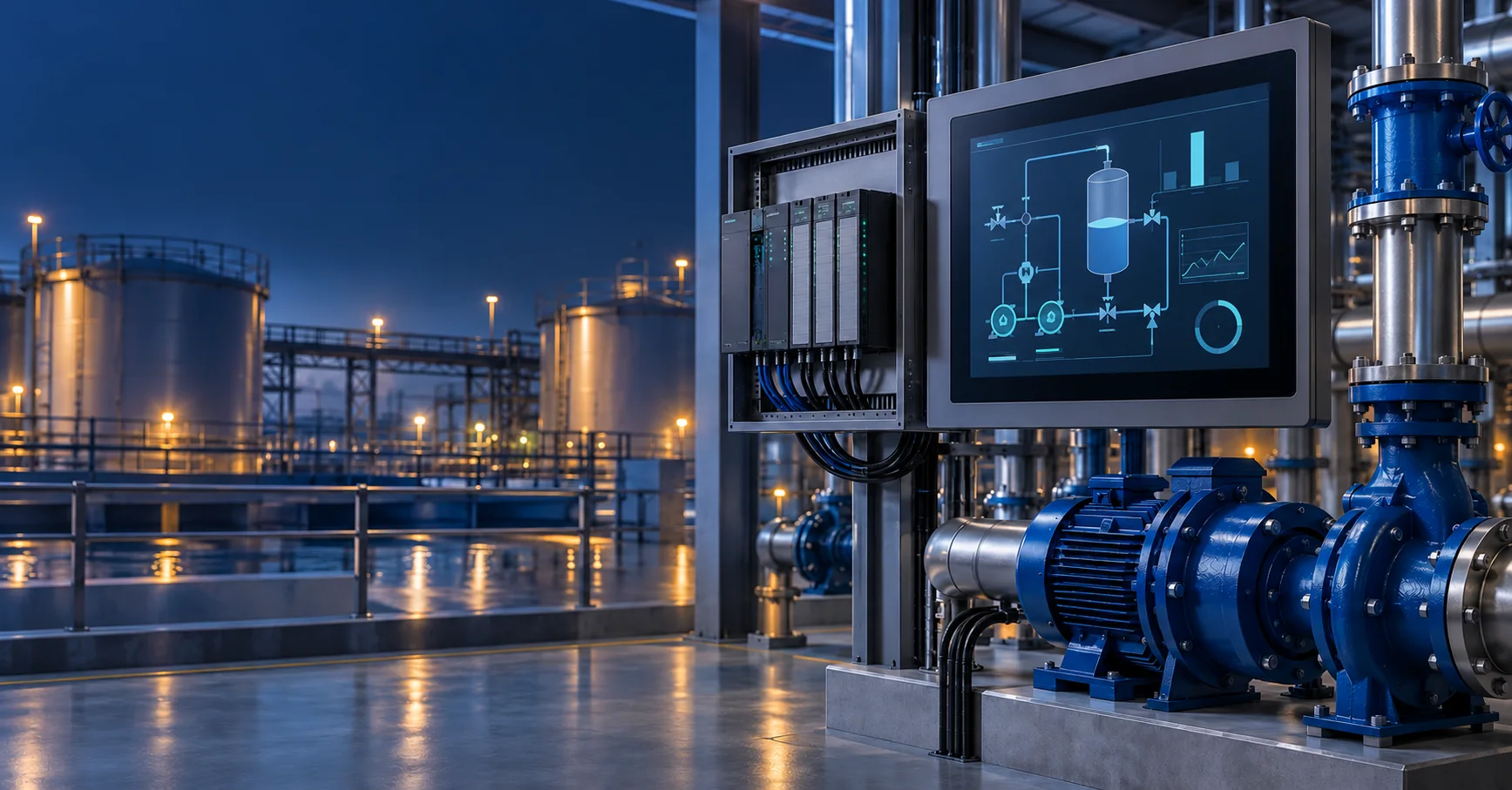
The fire scenario defines how the building and its installations should respond. Agreed assumptions are translated into a cause-and-effect matrix: input event, zone, activation conditions, sequence, feedback and fault response.
We assess fire detection, voice alarms, smoke control, ventilation, fire dampers, doors and shutters, access control, lifts, PWP isolation, gas detection and suppression together. The matrix also addresses maintenance conditions, line faults, power loss and communications failure. A single generic scenario is not suitable for every building.
Programming and integration implement agreed timings and priorities, supervised interfaces and clear signal identification. Testing must confirm the result at the final device: sending a command does not prove that a door has closed or a fan has started.
07 / DATPOL
Fire doors, shutters and compartmentation
The scope includes fire doors and shutters, curtains, fire dampers, closers, hold-open devices and position feedback. Selection follows the compartment function, required classification and documentation for the particular assembly.
Checks cover hold-open release, leaf-closing sequence, clear movement paths, seals, hardware and power-failure behaviour. Access control must not prevent required evacuation. Changing a lock or actuator, or drilling a door, requires confirmation that the approved configuration is maintained.
Cable and service penetrations must preserve the required compartmentation function. Acceptance includes identification, product documentation and integrated fire-system tests.
08 / DATPOL
Fixed fire suppression systems
Fixed suppression selection depends on the materials, enclosure geometry, occupancy, evacuation arrangements and acceptable consequences of discharge. Water-based, water-mist, gaseous and other specialist systems are considered where appropriate. Not every building requires fixed suppression, and no single agent suits every hazard.
The design covers detection and release, warning, agent distribution, conditions needed for effective suppression, status supervision and interfaces. Water systems require assessment of the water source and performance; gaseous systems require enclosure volume, integrity, pressure relief, occupant safety and post-discharge procedures.
Requirements for particular fixed suppression systems are assessed, among other provisions, under § 27 of the Polish fire-protection regulation. Delivery scope, equipment documentation and specialist contractor involvement are agreed for the selected technology.
09 / DATPOL
Server-room and IT-room suppression
Server-room protection is coordinated with detection, cooling, rack layouts, raised floors and ceiling voids. The scope identifies whether the whole room, a defined volume or an individual cabinet is protected, and the required response of IT power and ventilation.
- Agent and system selection against the design, operating conditions and applicable environmental restrictions.
- Early detection, agreed alarm-confirmation logic and release sequencing.
- Pre-discharge warnings, evacuation arrangements and the controls specified for the system.
- Enclosure integrity, required retention performance, pressure-relief arrangements and service penetrations.
- Integrated testing, safe re-entry procedures and restoration of protection after discharge.
Gaseous suppression does not mean a room is safe for people during discharge. Risks from the agent, atmosphere and fire products require assessment. Documentation and acceptance tests must reflect the actual enclosure.

10 / DATPOL
Electrical switchboard and cabinet suppression
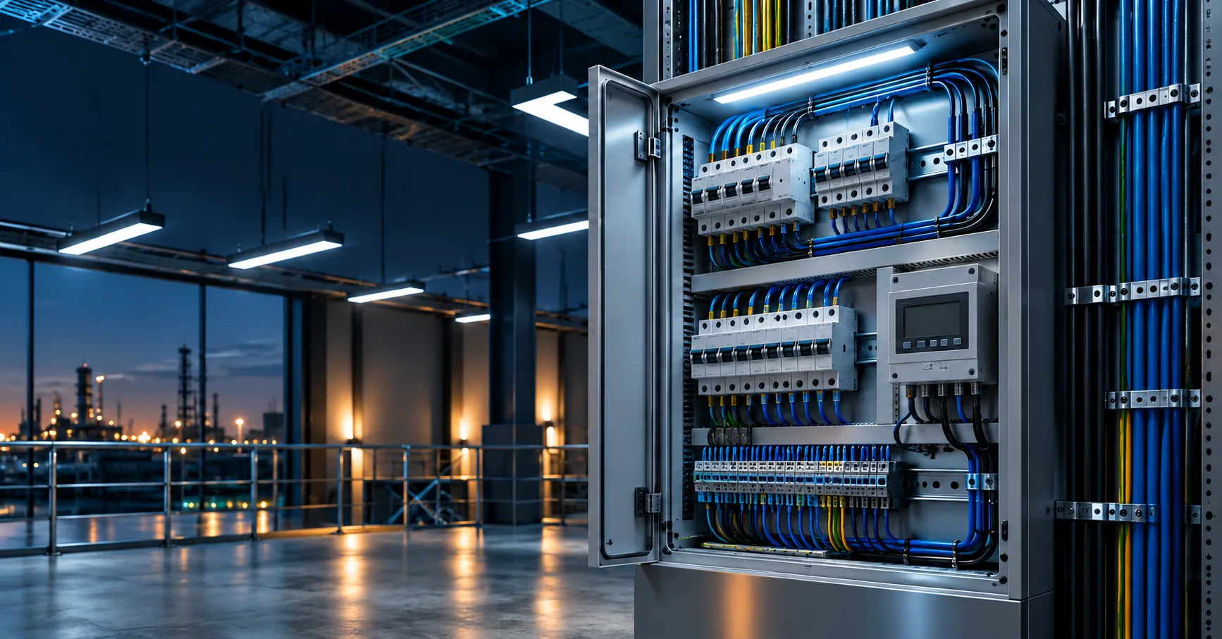
Local suppression is selected for switchboards, control cabinets and particular equipment by assessing ignition sources, voltage, volume, enclosure integrity and ventilation. Installing a suppression module does not remove the cause of an overheating electrical connection.
We assess compatibility with electronics, possible discharge residues, suitability for energised equipment and re-ignition risk. The design defines detection, alarm, power-isolation and release interfaces. Air ingress, open penetrations and running fans can reduce protection effectiveness and require particular attention.
The scope can include electrical diagnostics, thermal imaging, cable-route improvements and system supervision. Protecting one cabinet does not replace required room protection.
11 / DATPOL
Gas detection — GAZEX and related systems
The system is selected for the substance, concentrations, environment and required response: warning, ventilation or gas shut-off. Methane, LPG and carbon-monoxide detectors are not the same device. Locations follow documentation, emission sources and gas movement.
For example, GAZEX MD modules work with specified detectors and, in appropriate versions, a shut-off valve. Detectors, panels and valves must not be combined without compatibility checks.
- Boiler rooms, kitchens, plant rooms, garages and industrial installations, according to the actual hazard.
- Thresholds and delays, audible/visual indication, supplies and fault signals.
- Detector checks using test gas under the manufacturer’s procedure, calibration and sensor replacement.
- Valve-closure feedback where provided, and a safe procedure for restoring operation.
Hazardous areas require appropriate Ex selection throughout the installation. GAZEX identifies a manufacturer’s product family, not universal approval of every configuration.
12 / DATPOL
Standalone smoke, CO and gas alarms
We select alarms for the actual hazard and plan positioning, installation, testing and end-of-life replacement. A smoke alarm does not replace a CO alarm, and a CO alarm does not automatically detect a fuel-gas leak. Combined devices must have documented suitability for each claimed function.
Polish § 28a duties: standalone smoke alarms are required in dwellings and specified residential rooms or units providing hotel services. The provision includes an exemption where protection is provided by a fire-alarm system or automatic fixed suppression. CO alarms concern specified rooms with fuel combustion in dwellings or occupied commercial premises within a ZL fire zone; exemptions include certain sealed-combustion appliances and gas cooking appliances.
For relevant premises already in use before 23 December 2024, transitional dates are 30 June 2026 for covered hotel accommodation and specified rooms in commercial premises, and 1 January 2030 for existing dwellings and the specified rooms within them. New premises within scope do not benefit from these extensions.
Source: the regulation of 21 November 2024, § 28a and transitional provisions. Smoke and CO alarm requirements do not create a universal fuel-gas alarm requirement in every dwelling. Standalone devices are installed and maintained under manufacturer instructions; § 3(3a) excludes them from § 3(1)–(3).
13 / DATPOL
Remote panels for administrators and end users
Remote status visualisation can be included where the manufacturer provides a suitable interface and the design permits integration. Administrators can receive a multi-site view, while end users see only their assigned location and information.
- Panel, zone and device states: normal supervision, alarm, fault, disablement and unavailable communication, according to the source system’s capabilities.
- Timestamped events, maintenance records, inspection dates, reports and documentation.
- Individual accounts, roles, customer separation, operation logging and protected remote access.
- Service notifications, such as SMS and email, with agreed recipients and response arrangements.
The portal is a supervisory layer. Internet loss must not prevent local alarms and required fire controls. Alarm reset, detector disablement, releasing fire closures or initiating suppression are not default customer-portal functions. Any remote operation requires compatibility with system documentation, the design, procedures and appropriate authorisation.
Signals, update intervals, retention and notification handling are agreed before integration. The portal does not replace required site staffing, the fire control panel or mandatory transmission to the Polish State Fire Service.
14 / DATPOL
Fire alarm visualisation for operators and control rooms
Operators need to see where an event has occurred and what response it requires. We design and implement fire-system visualisation workstations for security teams, reception desks, control rooms and technical staff. Manufacturer software or an integration platform is selected for the panels, available interfaces, site scale and operating procedures.
- Building and floor plans: locations of detectors, manual call points, zones and actuators, with navigation from the site overview to an individual room.
- Clear event handling: distinct alarm, fault, disablement and communication-loss indications, event times and source identification. Priorities, queues and annunciation depend on the selected platform.
- Operator instructions: agreed procedures, contact details and documentation. Acknowledging an event in the visualisation is distinguished from resetting an alarm at the fire control panel.
- Multiple sites and workstations: views matched to duty and responsibility, individual accounts, permissions and operator activity records.
- System interfaces: display of available smoke-control, fire-closure, suppression, gas-detection and power-supply states. Events can be linked to relevant CCTV views where the systems support integration.
- History and analysis: filtering by site, time and device, reports and maintenance information. Time synchronisation, retention and the data recorded are agreed during design.
From workstation design to operator training
The scope includes panel compatibility assessment, licences and interfaces, preparation of plans and symbols, point mapping, workstation configuration and testing of events and communication loss. We verify that plan indications match the actual devices. Handover includes instructions, configuration backups and operator training; ongoing support includes plan updates following installation changes.
We agree standby power for the workstation, data backups, connection supervision and any required redundancy. Missing current data must be clearly indicated: a retained last-known state must not imply a healthy connection.
The operator workstation and DATPOL Control
DATPOL Control can supplement local visualisation with an agreed technical view for multi-site administrators: states, events and reports. Opomiarowani adds environmental and energy measurements. The data exchange scope is assessed for each installation rather than assuming compatibility with every panel.
Visualisation supports operators; it does not replace the fire control panel or required alarm transmission. Commands affecting protection, including resets, disablements and equipment activation, are enabled only where provided for by the manufacturer, design and procedures, with appropriate permissions. Workstation or Internet failure must not prevent autonomous fire-system operation.
15 / DATPOL
Installation, commissioning and acceptance
- Preparation: approved documents, schedule, operator arrangements, protection during disablements and coordination with other trades.
- Installation: equipment, circuits, routes, supports and penetrations according to the design, with identification and documented changes.
- Commissioning: addressing, descriptions, permitted threshold and control configuration, power and battery checks.
- Testing: detection, manual activation, alarms, faults, standby supplies and final-device response.
- Integration: cause-and-effect testing with the contractors responsible for interfacing installations, including feedback and failure behaviour.
- Handover: test records, as-built documents, product documents, configuration backup, instructions, training and named operational responsibilities.
Tests capable of releasing extinguishant, stopping a process or interrupting power require an agreed procedure. Functional acceptance cannot rely only on a green panel indicator.
16 / DATPOL
Maintenance, inspections and fault repairs
Maintenance schedules follow the system type, manufacturer instructions, operating conditions and relevant standards. Work can include detection, alarm and control tests, standby power, wiring and actuator checks, cleaning and replacement of life-limited components.
For fire-protection devices, Polish § 3(2)–(3) requires inspections and maintenance at manufacturer-defined intervals and at least annually. Shorter required inspection and testing cycles still apply. Standalone smoke and CO alarms follow the separate arrangements in § 3(3a).
Reports identify the scope checked, test limitations, faults, remedial priorities and completed repairs. Change history and fault-reporting arrangements are maintained. Changes of tenant, racking, ventilation or process require review of whether protection still matches the hazards.
17 / DATPOL
Polish regulations, standards and documents
The starting point is the individual building. Its industry alone does not establish a requirement for every system. We review legislation, documentation and the design; existing buildings also require consideration of changes and transitional provisions.
- The Polish Ministry of the Interior regulation of 7 June 2010, consolidated in Journal of Laws 2023, item 822: § 2 — fire-protection devices; § 3 — design, tests, inspections and maintenance; § 27–29 — suppression, detection and voice alarms; § 37 — explosion hazard assessment.
- 2024, item 1716: standalone smoke and CO alarms, exemptions and transitional dates, among other changes.
- 2026, item 1276: a subsequent amendment concerning shelter-point signs, which does not remove the maintenance duties described here.
- CNBOP-PIB guidance: product documentation and placing products on the market and into use. CE marking, declarations of performance and approval certificates are not interchangeable.
Designs identify the relevant parts and editions of standards: PN-EN 54 for fire-alarm components, including part 20 for aspirating detection; PN-EN 12101 for smoke and heat control; appropriate suppression standards such as PN-EN 15004 and PN-EN 12845; and standards for standalone alarms. Naming a standards family does not demonstrate compliance of an entire installation.
Current legal basis and responsibilities
Sources checked on 8 October 2026. ELI marks the former building technical conditions, Journal of Laws 2022, item 1225, as deemed repealed from 21 September 2026. We therefore do not present former thresholds and clauses as unconditionally current requirements for every project. The applicable basis and transitional provisions must be established for each undertaking. This service description does not claim every manufacturer authorisation or replace required approvals; competence and specialist involvement are confirmed for the agreed works.
This British English offer concerns projects in Poland. References to Polish legislation are not a claim of compliance with UK requirements.
18 / DATPOL
What should you prepare?
Send the site location, use and area, available drawings, hazards, existing systems and recent inspection records. Suppression assessments also need information about protected equipment, volume, ventilation and occupancy; gas detection requires the substance and process conditions.
We agree the survey, design, installation, upgrade or maintenance scope and whether remote visualisation is needed. Quotations separate design, approvals, equipment, installation, testing and maintenance. Delivery dates, support hours and response times follow the agreed contract.
Plan the next step.
A new system, an upgrade or a maintenance plan? Send the site details and available documentation.
[email protected]
+48 55 621 29 29